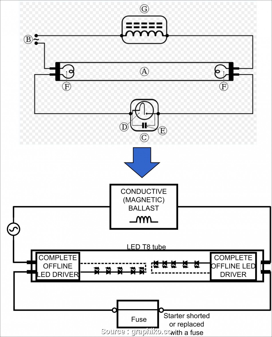
Ballast Bypass Wiring Diagram
Ballast Bypass Wiring Diagram. Install the bracket and the lamp. Direct wire ballast bypass led lighting, or ul type b, solution works directly from the line voltage flowing into the sockets.

In general, the hot wires are black, and the neutral wires are white. Werker t8 bypass led wiring diagram. This book even contains ideas for added.
9)reinstall the ballast cover to hide all wires.
Reinstall the ballast cover to hide all wires. In any case, once you identify the hot wire, the neutral will be on the same side. These are input wires because they send power to the fixture.
Disconnect main power before installation.
See figure a for typical ballast configurations. Remove the ballast from the tube lamp housing, and save the original wiring that connected to the vac. This led tube is a “ballast bypass” lamp that operates at line voltage.
4x6 led headlight wiring diagram;
Make a close cut and ensure that there are no longer than 2 inches of wires left. You need to cut these wires close to the ballast; You can either remove the ballast or keep it, it’s not useful in this case anyway.
Instant start ballasts can only be wired in parallel according to the diagram on the ballast.
Cut back additional wiring on opposite side of ballast as the led tube lamp only requires power at one end. Let’s pause for a brief summary of steps 3 and 4: Wiring diagram how to bypass ballast for led tube.
After cutting the wires providing input to the ballast, cut the neutral and hot.
1 lamp rapid start ballast diagram. Cut all existing connections to ballast as shown below and remove ballast. 240 volt 3 wire (split phase) ballast bypass wiring instructions and diagram posted by sam t on 4/27/2017 to led parking lot lights so you are trying to change to led lights with 240volt but now you have 2 hot wires and a neutral/ground coming out of the building.
Post a Comment for "Ballast Bypass Wiring Diagram"