Alternator Charging System Wiring Diagram
Alternator Charging System Wiring Diagram. These directions will be easy to grasp and apply. Diagram of an alternator wiring auto fault finder facebook voltage regulation 101 with diagrams in the garage carparts com update car charging system construction battery charger electrical wires cable png pngegg wilbo666 toyota alternators tech engine a series rollaclub free work manual brush regulator several years transport pngwing automotive ac.
Be sure not to connect the balmar alternator on the ground at any part of the system because it will be not ground isolated anymore! Please refer to the manual and wiring diagram that came with your alternator for more specific details. All modern charging systems use some form of regulation that’s purely electronic.
All modern charging systems use some form of regulation that’s purely electronic.
Clip clammeter (a on diagram below) onto the alternators main charging lead, as far away from the alternator as possible (keeps it clear of magnetic fields that can cause incorrect readings). Acronyms on the system, but relatively the definitions are the same. Alternators involve complex wiring, and the wires must be connected to the correct units and terminals.
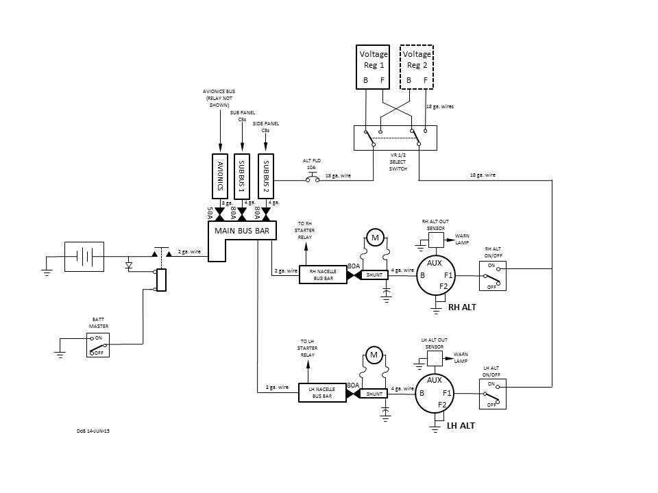
A typical alternator wiring diagram with an external electromechanical voltage regulator.
These guidelines will likely be easy to grasp and apply. Alternator doesn t charge regulator or battery. My build engine and charging system connections es.
Diagram of an alternator wiring auto fault finder facebook voltage regulation 101 with diagrams in the garage carparts com update car charging system construction battery charger electrical wires cable png pngegg wilbo666 toyota alternators tech engine a series rollaclub free work manual brush regulator several years transport pngwing automotive ac.
This wiring configuration will excite the alternator to start charging when the engine is running at low rpm s. Wiring diagrams provide a visual representation of the connections and physical layout of the circuit. It’s supposed to assist all the typical user in developing a suitable method.
• ig is the ignition input that turns on the alternator/regulator assembly.
• s is used by the regulator to monitor charging voltage at the battery. Jcb 530 120 563714 1990 model i was seeking a wiring diagram and could manulipate the loom with single wires from. This can be simplified by creating alternator wiring diagrams.
Here the basic internal circuit diagram of the car alternator and the wiring diagram of the alternator with battery is given below.
There are four wires going into this alternator. Charging system mitsubishi forums com. 13 alternator battery charger circuit diagram.
Post a Comment for "Alternator Charging System Wiring Diagram"