1492-ifm40f-2 Wiring Diagram
1492-ifm40f-2 Wiring Diagram. Compatibility — to ensure proper operation with the i/o module, do not exceed the voltage and current ratings of the ifm. 2 for operation from a single power source connect com0 through com15 terminals together and connect +v0 through +v15 terminals together.
Wiring — refer to the label section on page 174. From the table above to the end of the cat. Compatibility — to ensure proper operation with the i/o module, do not exceed the voltage and current ratings of the ifm.
Fusing — fuse holders are included with the ifm.
Discover how the 1492 i/o wiring system can ease your migration journey from slc™ 500 to compactlogix™ 5380 control systems. Included is a diagram for a 3 way dimmer and an arrangement to for 3 way outlet control from two locations. Learn how to avoid the risks.
Pinout diagram using cable**n3 with ib32 input module.
Fuses (5 x 20 mm) are not included. 1492 wiring systems solution you simply mount the interface module (ifm) onto a standard din #3 rail. 2 for operation from a single power source connect com0 through com15 terminals together and connect +v0 through +v15 terminals together.
Literature library | rockwell automation
Wiring — refer to the label section on page 174. Isolation — the fuse clips and blown fuse indicators are isolated into 16 groups of terminals. Wiring — refer to the label section on page 174.
‹ view all i/o wiring and conversion systems.
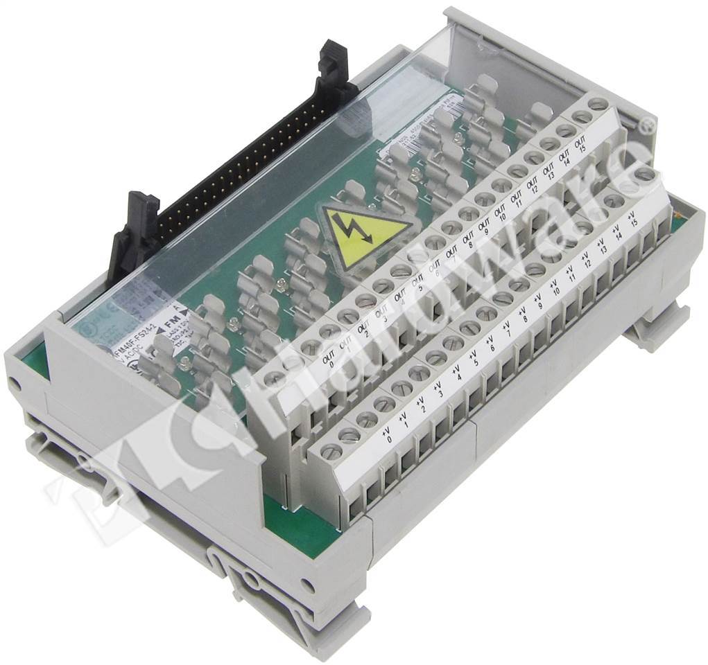
Groups a, b, d, and d. Wiring — refer to the label section on page 181. Interface module, digital, isolated fusible, 40 point, 5 x 20 mm fuse clips 24 volt ac/dc, blown fuse indicators, extra terminals for outputs, cat #:
Compatibility — to ensure proper operation with the i/o module, do not exceed the voltage and current ratings of the ifm.
Fuses (5 x 20 mm) are not included. Compatibility — to ensure proper operation with the i/o module, do not exceed the voltage and current ratings of the ifm. On this page are several wiring diagrams that can be used to map 3 way lighting circuits depending on the location of the source with relation to the lights.
Post a Comment for "1492-ifm40f-2 Wiring Diagram"