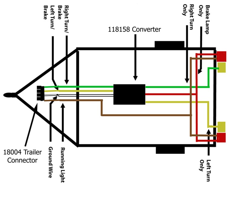
Combined Brake And Turn Signal Wiring Diagram
Combined Brake And Turn Signal Wiring Diagram. At this point run your wires to the rear lights. Find this pin and more on sonny's stuff by brenda wilson.

Wiring diagram turn signals and brake lights wiring diagram is a simplified standard pictorial representation of an electrical circuit. On the output side you will have the yellow wire for left turn signal only, green. A diode is just a gate.
Connect the wire from right turn and stop to the green wire input side.
Since the turn signal uses the same filament as. Wiring diagram also provides beneficial suggestions for tasks which may demand some added equipment. One brake light fitted up to ts15601, may, 1957, for us market.
Curt makes a module designed to separate the circuits for trailer lighting.
On the output side you will have the yellow wire for left turn signal only, green. Heres the 82 pontiac rwd car shop manual wiring diagram for the turn signal switch. 1 trick that we 2 to printing a similar wiring plan off twice.
Need to know the function of two wires.
Variety of universal turn signal wiring diagram. L turn/brake , r turn/brake, tail lights, ground. Runs your wires into the converter and coming out of the converter will be four wires.
But, it does not mean link between the wires.
At times, the wires will cross. Only one switch fitted prior to this change. Combined brake and turn signal wiring diagram.
When you turn a signal on, the turn signal switch will disconnect one rear bulb from the.
Find this pin and more on sonny's stuff by brenda wilson. For me the easy way would be to just run a third light for my brake light. The wire from the brake light switch (should be white) needs to be wired into the turn signal switch instead of going directly to the brake lights.
Post a Comment for "Combined Brake And Turn Signal Wiring Diagram"